|
Please read through our Frequently Asked Questions
lists before contacting support. If you do contact and don't hear back,
it's likely because we've already answered it here. FAQ (Frequently Asked Questions)
Q. Can I order just a body, power supply, cable,
grill, capsule, circuit board or any other individual part?
A: The
only items we offer for-sale are listed on the website, which include
A460 and A5500 body only kit, and A5500 PCB only kit. We will add more
individual parts in the future and when they are avalable for
sale, they will be listed on our website. Q: Where's my order? When will my order ship? A: Unless otherwise stated at the top of our website, we typically
ship within 2 days of your order
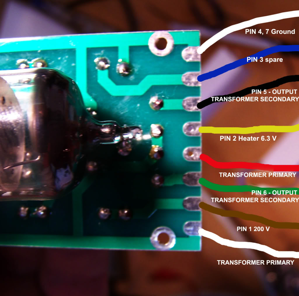
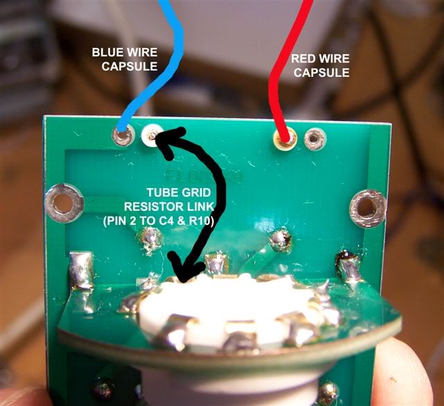
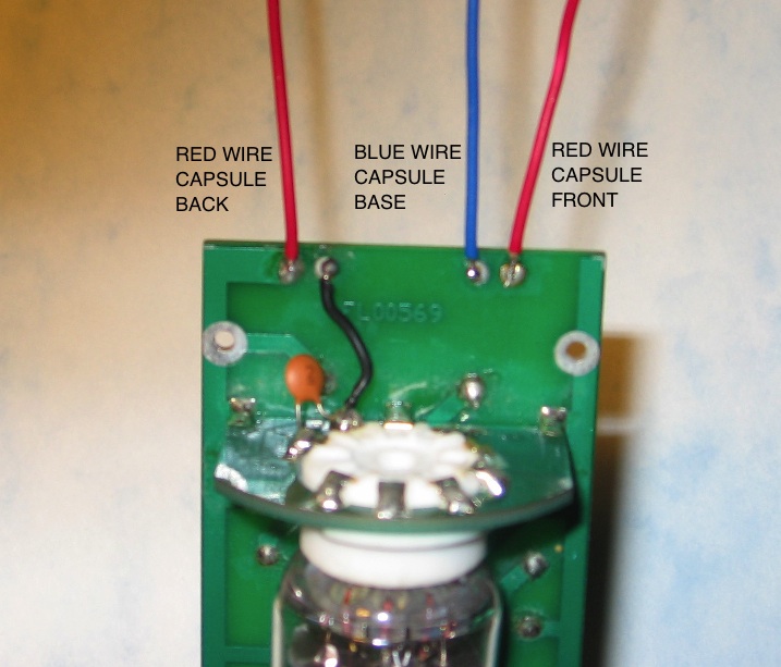
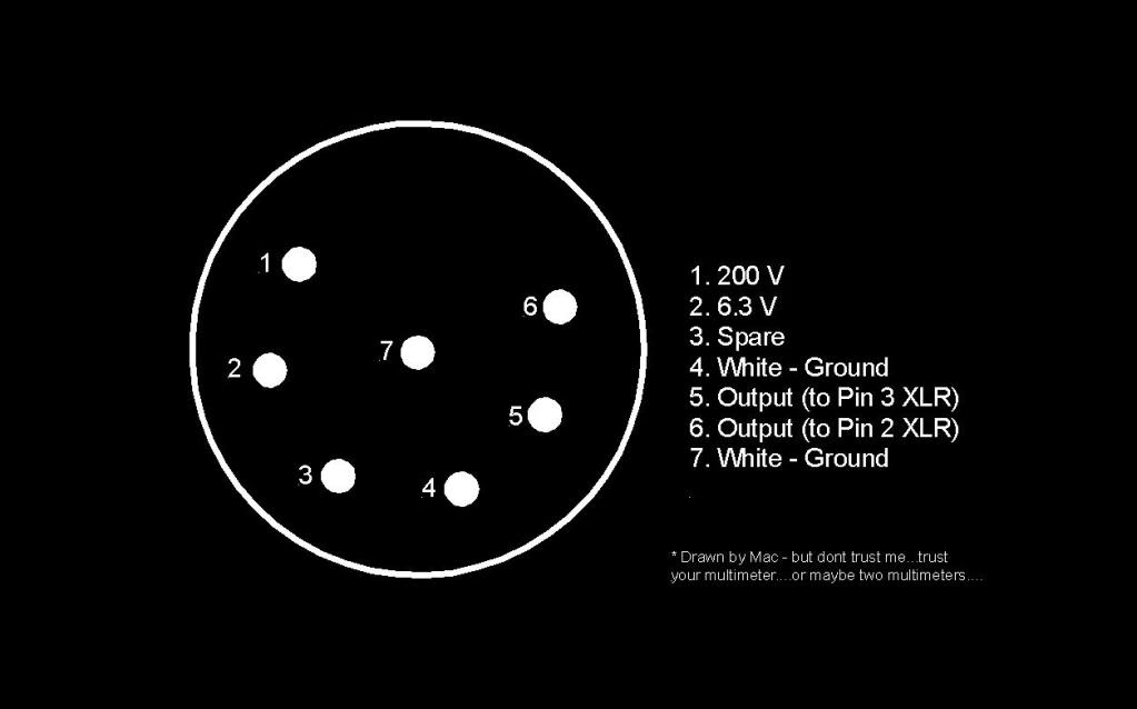
being placed. The A5500 PCB only kit is shipped by first class package. Q: Can you rush ship my order? A. Sometimes we can ship the same or next day and send expedited for an additional cost. Please contact us at info at Aurycle.com and wait for a reply. Some things to consider. All kits and microphones are shipping from the PST timezone. USPS pick is before 11 AM noon. You must get acknowledgment and have paid for your order before 10:00AM PST on the same day otherwise it won't ship until the next day. Q: We are often asked for estimated shipping costs for our DIY kits. A. Below are some estimates for the shipping cost world-wide (rate may be slightly more or less depending on your country): 460 DIY kit: one for $22.00, two for $31.00 460 Body Only DIY kit: one for $22.00, two for $31.00 A5500 DIY kits and A5500MP DIY kit: one for $40.00, two for $53.50 These rates are for United State Postal Service Priority Service approximately 6 to 20 business days for delivery. We will refund any over charges for shipping after we receive your payment. Q: What are the advantages using a USB microphone over using computer built-in sound card? A: There are several advantages. One of them is that using a USB microphone you get high-quality recorded sound. The reason is simple: the built-in sound card is not designed for high-quality sound recording. The high-end cut-off frequency of those sound cards is lower, sometimes much lower, than 20,000Hz. To see this, you can do a simple test. Download a free sound editing software, Audacity. Choose the built-in microphone as your recording device. Say "sssss" (like that in kiss) for a few senconds and record it. Then highlight a segment of the signal and go to Analyze->Plot Spectrum. You will see a frequency response curve window pops up, and from which you can easily figure out the high-end cut-off frequency. I have tested it for an IBM and Mac laptop computer. For IBM T43P, the cut-off frequency is about 7000Hz, while for the Mac, it is about 18,000Hz (Mac is meant to be good for music). But with our USB microphones (A460U, A620U, and A630U), the spectrum goes well above 22,000Hz. I wish I could post these spectrum graphs here, because it is really amasing to see the differences. But it would be more convincing if you do it yourself and see it with your own eyes on your own computer. Q: Do you offer schematics and unpopulated PCB's only? A: Yes, we offer unpopulated PCB only for A5500. The schematics for this kit are available on our website http://www.aurycle.com Q: Do you have a shock mount that will fit the a5500 DIY Tube Microphone kit? A: Yes, please check the link: Shock Mount BZJ-10 Q: Are the A460 bodies the same as the A570t bodies? A: The bodies and internals of the A570t and the A460 are not the same. There is slightly more space for a circuit in the A570t because it is a transformless microphone, therefore there is not space for a transformer. See attached picture. The black microphone is the A570t. Q: How do I wire the A5500 or A5500MP XLR connector to the circuit board? A: See the image below for location of the wires Q: How do I wire the A5500 capsule to the circuit board? A: See the image below for location of the wires Q: How do I wire the A5500MP capsule to the circuit board? A: See the image below for location of the wires Q: What is the pin-out for the A5500 or A5500MP XLR connector? A: See the image below Q: How can I tell if PSU is working correctly? Disclaimer: We recommend not performing these steps if you are not experienced with electronics. Proceed at your own risk! A: The PSU shipped in the DIY kit supplies two DC power sources to the microphone. One is the low voltage about 6.3V to the filament of the tube to heat the cathode, and the other is the high voltage about 200V to the anode of the tube. To determine if the PSU works fine, we need to measure these two voltages. They can be measured most easily on the PCB in the microphone. Please be aware that there are two versions for both A5500DIY and A5500MP DIY. If the voltages are about 200-250V on pin 1 (version 1), or 300-350V on pin 3 (version2), and 6.3V for pin 2, you are done. The PSU is fine. If not, you need to figure out if the problem is on the PSU or on the microphone, because something wrong in the circuits of the microphone will affect these two voltages even the PSU is OK. Please follow the steps shown below to figure out if the PSU is working fine. Because the high voltage and high current are involved, there will be a danger of electrical shock which might be life threatening or a potential damage to the PSU. Please pay an extremely close attention to the following steps. If you are not sure you can safely perform it, please stop. 1. Turn OFF the PSU. 2. There is a 115/230V power selection switch on the back of the PSU. Set it to the right position matching your local AC power supply. Setting this switch wrong may damage the PSU and the microphone. 3. Disconnect the 7-pin cable from the 7-pin female connector on the PSU. 4. Look at the female 7-pin connector on the front of the PSU closely to see which pin is pin 1, pin 2, and pin 3. 5. If the rod of the multi meter is too thick to reach the metal pins in the connector, insert a short metal wire with a proper diameter into pin 2 to make a connection to the pin. Caution before proceding:
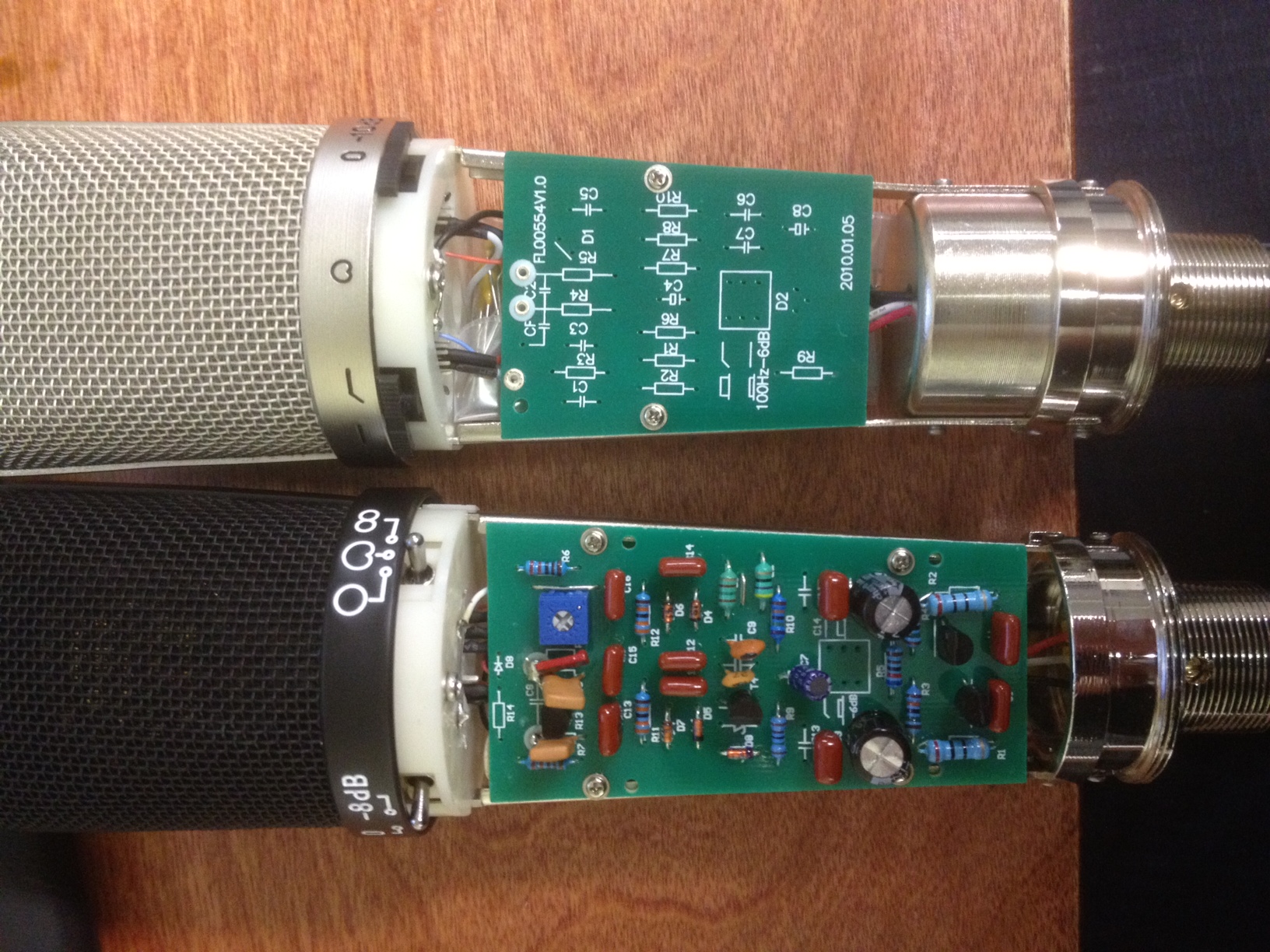
6. Turn on the PSU. 7. Measure the DC voltage between the pin 2 and the metal housing of the connector. Because the output current of the pin 2 is very high, be careful not to cause any short circuiting, which will damage the PSU. The voltage should be about 6.3V and steady. 8. Turn OFF the PSU. 9. Remove the wire from the pin 2 if you use one, and insert it to pin 1 (for version 1) or pin 3 (for version 2). 10. Turn on the PSU. 11. Measure the DC voltage between the pin 1 (for version 1), or pin 3 (version2), and the metal housing of the connector. Because it is a high voltage, be extremely careful to avoid an electrical shock. Your hands should never directly touch any metal part of the PSU during the measurement. The correct reading is about 200-250V (version 1) or 300-350V (version 2) and steady. Q: Where can I download the technical files for the a5500 DIY tube microphone? A: You may download them from the main Aurycle.com website. Q: Why do we need two ceramic insulators for the coupling capacitor C4? A: The resistor R10 provides the bias voltage to the capsule, and it is also the load resistor for the output signal from the capsule. Because the output impedance of the capsule is very high, R10 needs to have very large value. In A5500 DIY kit we use 1KM, that is 1000,000,000 ohm. If we solder this resistor directly to the PCB, the resistance of the PCB board itself, although it is an insulator in nature, is not large enough. That is why we put a ceramic insulator there. The same argument applies to the resistor R6, which is the grid resistor for the tube. Q: How to install the two ceramic insulators to PCB? A: Add a little super glue on the insulators then put them on the PCB, and wait for the glue to dry. When you solder wires on them, be careful and quick. A: This capacitor can be used to tune the gain of the tube amplification. If you think the gain is too high (the output signal from the microphone is too large), you can put a 2p, 3p etc capacitor between the plate and the grid of the tube. It provides negative feedback to the tube amplifier and will reduce its gain. Increasing the value of this capacitor will increase the feedback and reduce the gain more. In addition to the reduction of the gain, feedback also improves the non-linear distortion of the amplifier. A: No. One of the functions transformer provides is the impedance conversion. The output impedance of the tube is high, at the range of 100k ohm, but the requirement for the output impedance of the microphone standard is about 600 Ohm. Our transformer has a turn ratio of 10:1, and that means the impedance ratio is 100:1, which provides a good impedance match. If you swap the primary coil with the secondary one, the impedance ration will be 1:100, which is not allowed. Q: How does the transformer convert unbalanced to balanced output? A: One of the functions the transformer provides is the conversion from unbalanced to balanced output. The white wire of the primary coil is connected to the ground, so it acts as an unbalanced output load that is required by the tube amplifier. While both black and green wires from the second coil of the transformer are not connected to the ground, so it provides a balanced output. Q: Why do we need to use balanced output for the microphone? A: Microphone's output will typically go a long way to reach the preamp. Although a shielded cable is used, outside interference signals will be picked up by the cable. Balanced output cable has two output wires in it, and the output signal of the microphone fed to the preamp is the difference between the two. If the two wires pick up the same noise signals, the difference of the two will be zero. A: It will not harm the microphone, but it will change the phase of the output signal from the microphone 180 degree. Unless you have a specific reason to change the phase (for instance, to match with an old microphone which has an out-off phase output), do not do it. Q: Does the PSU work with both 230v/50Hz and 115v/60Hz? A:
Yes, the PSU included with the DIY mic kit has a switch on the back and
will work with both 230v/50Hz and 100 to 120v/60Hz power sources.
|